Water spray fire and explosion mitigation (SWSM)
- 15 May 2025
- 5 Minutes to read
Water spray fire and explosion mitigation (SWSM)
- Updated on 15 May 2025
- 5 Minutes to read
Article summary
Did you find this summary helpful?
Thank you for your feedback!
Water deluge modelling in FLACS can be applied to fire and explosion scenarios to simulate water mitigation measures which affect the reaction rate (during explosions, only) and provide radiation shielding.
An example scenario is provided in the FLACS examples folder, ex08_water. The scenario is a pool fire at a biogas plant with water spray systems designed to shield neighboring critical equipment from radiative heat. The protected components include manure digesters, a biogas scrubber, a bio-LNG tank, and associated containers.
The setup employs a simplified LNG uncoupled pool fire model as the heat radiation source and evaluates different water spray system configurations.
The simulation is intended to demonstrate the capabilities of the water spray model and the various water spray configurations for mitigating radiative heat exposure via shielding.
The video below presents a walk through of the setup and is also detailed below.
Simulation details
The scenario involves four distinct spray model setups: three systems with non-uniform water distribution and one employing a uniform water curtain. The following areas are protected by water spray and are highlighted in the diagram below:
1a,b) manure digesters
2) bio-LNG tank
3) biogas scrubber
4) containers
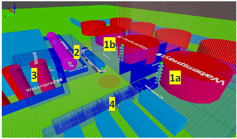
Geometry and computational domain of a biogas plant with pool fire and Static Water Spray Model setup.
Manure digesters sprinklers
The first system consists of two large-scale spray setups designed to protect the manure digesters (see ”1a” and ”1b” in figure above). Two bounding boxes are created:
Digester 1a
Position (-32, -35, 0)
Size (25 × 20 × 6) m
Digester 1b
Position (-12, -35, 0)
Size (25 × 20 × 6) m
The water spray shape is defined as a spray. Each setup uses sprinklers characterized by:
K factor = 80 [litre/min/bar 1/2]
operating pressure = 2 bar
spray cone angle = 130°
Using the recommended expressions to determine inlet water spray properties and a discharge coefficient of 0.9, the calculated parameters include:
nozzle diameter = 10.6 mm
initial velocity = 19.9 m/s
volume flow rate = 113 L/min
droplet size = 765 µm
Nozzle positions are define to create 13 sprinklers surrounding the digesters, mounted 5 m above ground level, positioned along half the circumference. The nozzles are spaced radially 1 m from the tank wall and 2 m apart from each other along the circumference.
Spray nozzles have been validated for attenuation properties in FLACS, see the Validation section of the FLACS User’s Manual for more details.
Note 1
While the nozzle position defines the spray’s location, the bounding box limits the spray’s computational domain.
Note 2
Although water may appear in the computational grids within the solid tank (which has zero porosity), such contributions are disregarded in radiation shielding calculations.
Attention
In reality, impinging water from a spray system would form a water film and provide a cooling effect. However, this consideration is not currently modeled in FLACS.
Bio-LNG tank
The second system protects the bio-LNG tank with a smaller-scale configuration. A bounding box around the bio-LNG tank is set as:
Position (-2, -10, 0)
Size (24 × 10 × 6) m
The water spray shape is set as a spray and the system uses nozzles with a sprinkler with operating conditions of:
Operating pressure = 6 bar
Nozzle diameter = 2 mm
Initial velocity = 31 m/s
Volume flow rate = 6 L/min
Droplet size: 165 µm.
A linear arrangement of 25 nozzles mounted 5 m above the ground and spaced 1 m apart is created.
Biogas scrubber
The third system uses the same nozzle type and operating conditions as the bio-LNG tank system but is arranged to protect the biogas scrubber (see ”3” in figure above). The water spray bounding box is set as:
Position (-7, -1, 0)
Size (8 × 8 × 9) m
Nozzle positions are defined to create two concentric rings of with 13 nozzles configured around the scrubber. The first ring is mounted at a height of 4 m, and the second at 8 m.
Containers
The fourth setup consists of water curtains with a uniform water distribution with 11 water sprays aligned in two rows, with five nozzles in the front row and six in the back row (see ”4” in figure above). The maximum height of the curtain is 2.5 m and the curtains are arranged every 4 m, i.e., overlapping by a metre at each end. The following parameters are set for the curtains:
Size (1.5 × 5 × 2.5)m
Mean droplet diameter = 400 µm,
Water volume fraction = 0.1 L/m³
Direction = +Z
For this type of spray shape, the positioning and dimensions are determined by the direction and shape of the bounding box (see curtain setup description).
Visualising the results
3D Plot
open the results file in Flowvis, creating a 3D Plot
From data selection select the following variables to display
Temperature_3D (isosurface) - to observe the fire
MassFractionFuel_3D (surface) - to display the pool leak
change the value range minimum to a very small non-zero value
WaterDropletsVolumeFraction_3D (volume) - to display the water spray in action
Set the fixed value range minimum to a very small non-zero value and the maximum to 0.1
Select Blues as the colour gradient to change the appearance of the water spray
VolumeFractionSoot_3D (volume) - to display soot generated from the fire
Use the time slider to observe when the water spray is activated
The following options can be selected for improved visualisation:
Turn on Shadows, Sky, Textured geometry, Realistic lighting
Turn off Grayscale
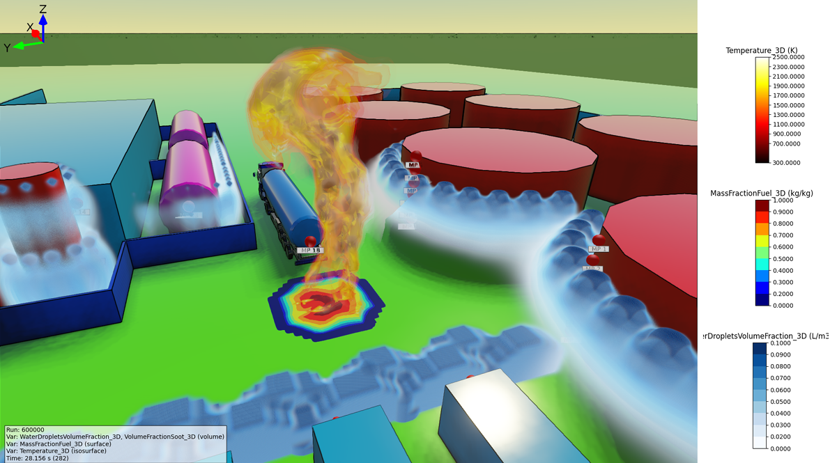
Instantaneous 3D plot showing isosurface contours of pool fire temperature, mass fraction of methane, and water droplet volume fraction.
Monitoring the radiative heat flux
A set of 18 monitor points were included in the example scenario setup in order to investigate the effectiveness of the applied water spray system. The following monitor points are included around the facility and around protected equipment:
1a) Monitor points #1-6 - behind the manure digester (1a) water spray
1b) Monitor points #7-12 - behind the manure digester (1b) water spray
2) Monitor point #13 - behind the bio-LNG tank water spray
3) Monitor points #14-15 - behind the biogas scrubber water spray
4) Monitor points #16-17 - behind the water curtain protecting the containers
5) Monitor point #18 - near the pool fire, without any shielding
To visualise the effectiveness of the applied water spray system, create a Scalar Time plot:
Add a new page, select Scalar Time and navigate to the results files (i.e. the scenarios with and without water spray systems).
Select appropriate variables, such as RadIncHeatFlux and plot for your desired monitor points.
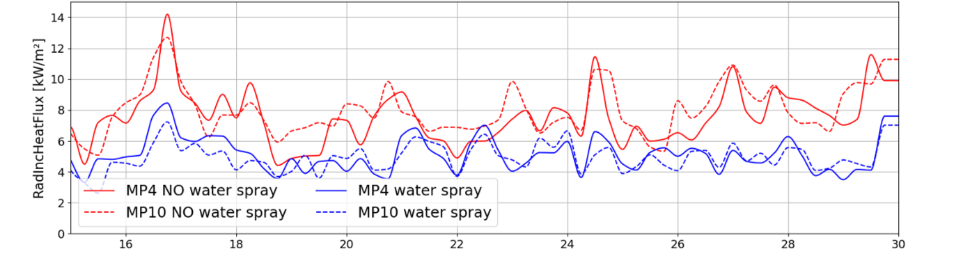
Incident radiative heat flux for selected MPs over time
Was this article helpful?