- 13 Mar 2025
- 3 Minutes to read
Geometry
- Updated on 13 Mar 2025
- 3 Minutes to read
The FLACS geometrical model is created within CASD via Geometry → Edit File. Within the geometry window, the user can manually build a geometry from primitives, import an existing geometry or import an external CAD file.
Primitives
Geometrical models in FLACS are made up of primitives. The following types of primitives are available in FLACS:
Box
Cylinder
Ellipsoid
General truncated cone (GTC)
Convex polyhedrons (CP8)
Torus
Rectangular torus
Mesh
Primitive types
Box
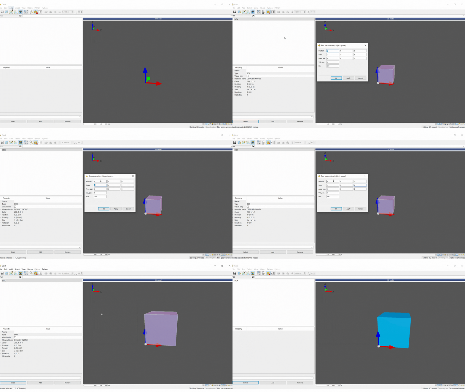
When defining a box, the position and size must be specified. A box can be created via Add → Box or pressing B on your keyboard.
Cylinder
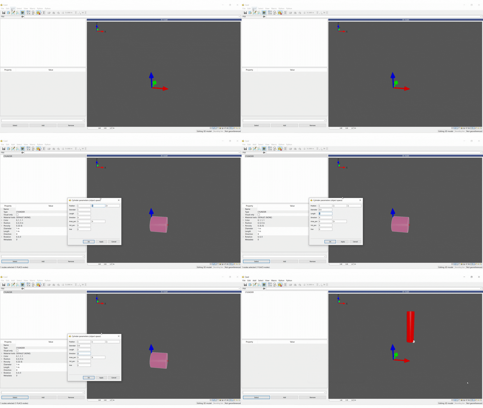
When defining a cylinder, the position, diameter, length and direction must be specified. A cylinder can be created via Add → cylinder or pressing C on your keyboard.
Ellipsoid
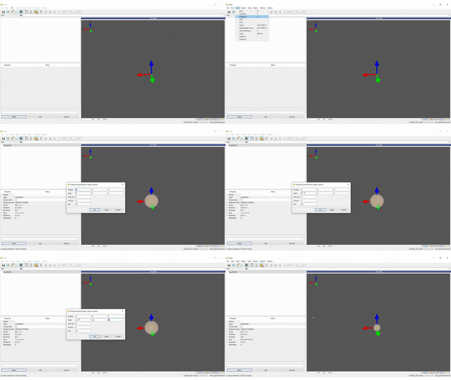
When defining an ellipsoid, the position and size must be specified. An ellipsoid can be created via Add → Ellipsoid or pressing E on your keyboard.
Mesh
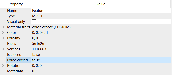
A mesh is a generic primitive that can take any shape. CAD files which are imported into FLACS are often composed of mesh primitives. Meshes can have the following properties:
Faces: number of faces in the mesh (not editable)
Vertices: number of points the mesh consists of (not editable)
Is closed: when set to true the mesh is a closed 2-manifold (not editable)
Force closed: when set to true the mesh will be forcefully interpreted by the porosity calculator as being closed.
Operations
Union
Creates a group (union) containing the selected primitives and operations. This will prompt the user for a group name, and put the selected items under a new top-level group.
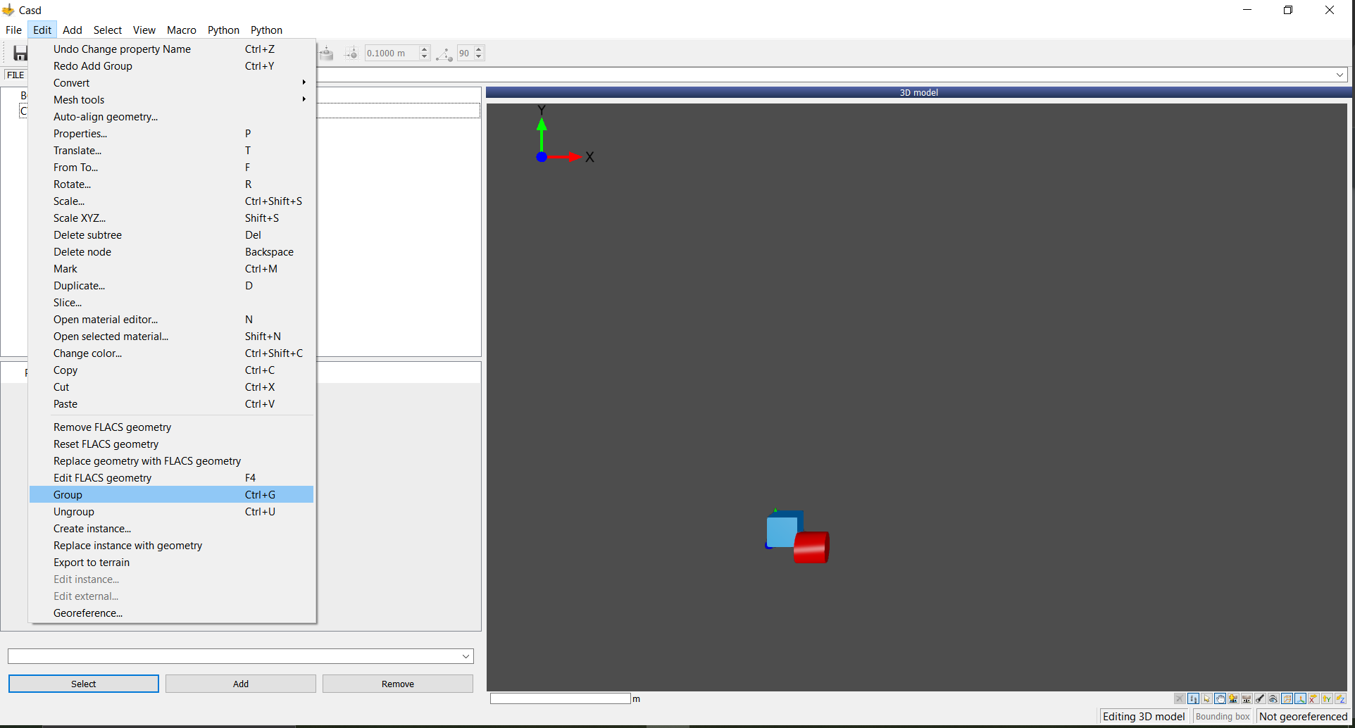
Primitives can be grouped via Edit → Group in the menu bar or by using the shortcut Ctrl+G.
Primitives can be ungrouped via Edit → Ungroup in the menu bar or by using the shortcut Ctrl+U.
Left difference
Left difference can be used to subtract objects from marked objects. To create a left difference:
Mark the object(s) that you want to edit using
Ctrl+MSelect the object(s) you wish to subtract
Add left difference via Add → Left Difference or by pressing
Lon the keyboard
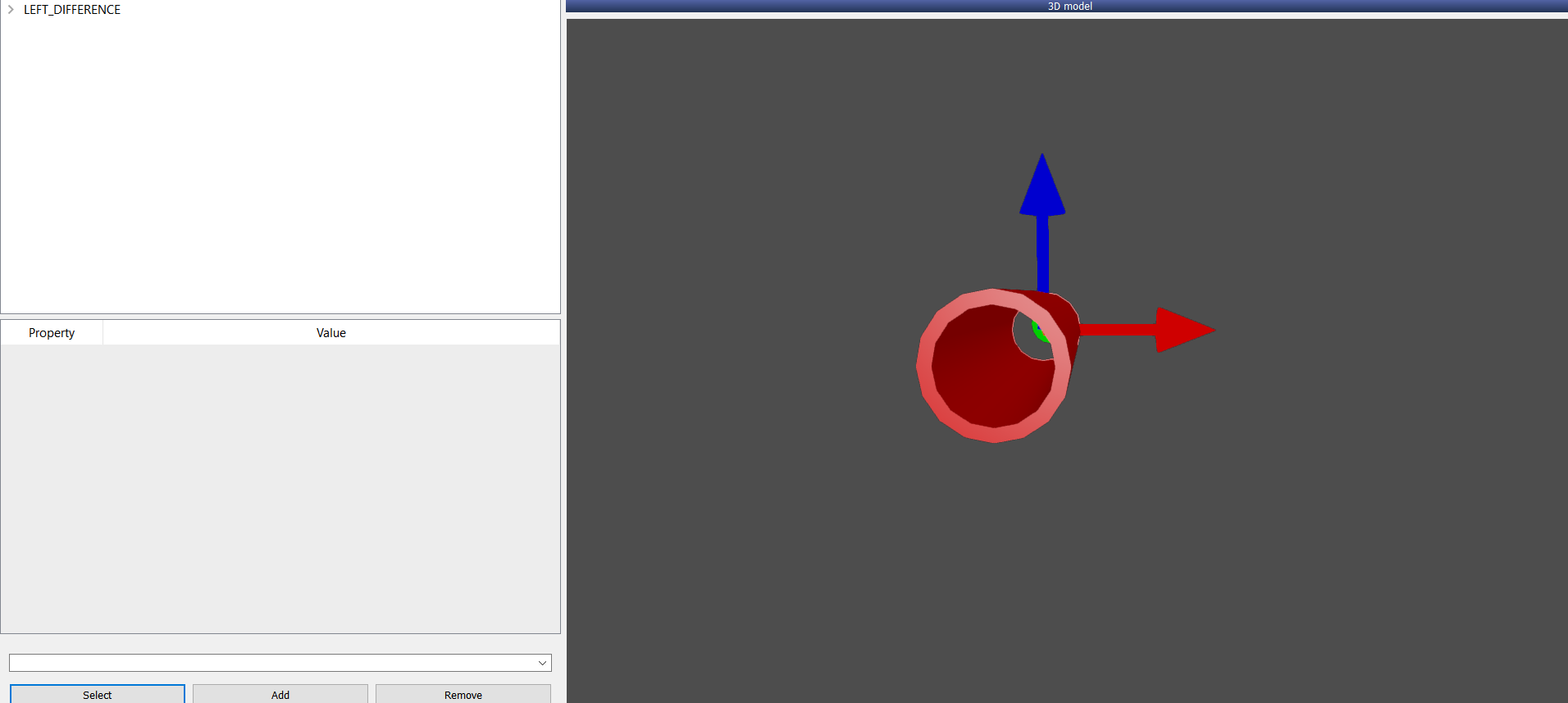
An example of a cylinder with a smaller cylinder subtracted from via using the left difference operation is shown below.
Other useful functions
An introduction to commands commonly used in the object window in CASD is provided below. For further details and for commands not described here see section 3.4 of the FLACS-CFD User’s Manual.
Scale
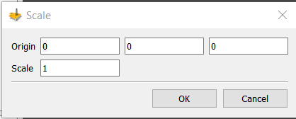
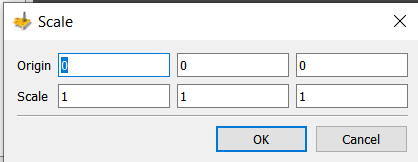
The scale command allows the user to scale selected objects. The command can be accessed via Edit → Scale or by the shortcut Ctrl+Shift+S. An origin for scaling and a scaling factor must be defined.
Scale XYZ
Similar to the scale command however, an object can be scaled independently in each direction. The command can be performed via Edit → Scale XYZ or by the shortcut Shift+S.
The origin for scaling must be defined along with a scaling factor for each axis.
Rotate
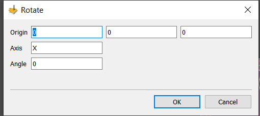
Rotate command can be used to rotate objects. The command can be performed by selecting the object(s) to be rotated and rotating via Edit → Rotate or by pressing the R key. An origin, axis and angle of rotation must then be defined.
Translate
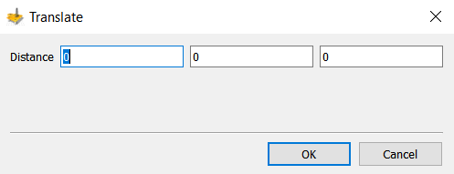
The translate command can be used to translate selected objects by a distance specified for each axis. The command can be performed by selecting the object(s) to be translated and pressing T or via Edit → Translate.
Duplicate
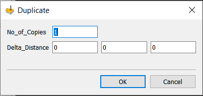
The duplicate command can be used to duplicate selected objects. Multiple duplicates can be created simultaneously. The number of duplicates along with the distance between each duplicate must be specified.
The duplicate command can be performed by selecting the object to be duplicated and pressing D or via Edit → Duplicate.
Edit Properties
The properties of object(s) can be edited by using the Properties command. This can be accessed by pressing P or via Edit → Properties. Multiple properties, such as dimensions and position can be edited by the command.
Porosity
When creating a primitive, volume and area porosities must also be defined:
Volume porosity: mean blockage of the inside volume of the control volume
Area porosity: blockage of the surface area of the control volume
A porosity value of 0 means that the control volume is completely blocked by the geometry, a value of 1 means that the control volume is completely open.
Importing CAD file(s)
CASD allows for a geometry import procedure using geo2flacs entirely from the graphical user interface which can be accessed via Geometry → Import CAD file(s).
Select Add input files to add the relevant files. The object type can then be set in the drop-down menu for each file.
Transformation parameters for rotation, translation and scaling can be filled in, if necessary. These correspond to the geo2flacs options-r, -t, and -s, respectively.
Filtering, grouping, and alignment options can also be specified.
Finally, a new or existing database directory needs to be picked for the geometry to be included in.
The alternative to running the geometry import from the GUI is to use the geo2flacs utility for manual geometry import.


