- 11 Jul 2024
- 4 Minutes to read
Data output
- Updated on 11 Jul 2024
- 4 Minutes to read
Data for simulation variables can be obtained by setting up monitor points, pressure relief panels and 3D output. The Simulation and output control tab allows the user to control the frequency of 3D field output as well as general simulation and output control. Gas monitor regions can be defined to measure several output variables including total fuel and equivalent cloud sizes across a line or within a specified volume.
Monitor points
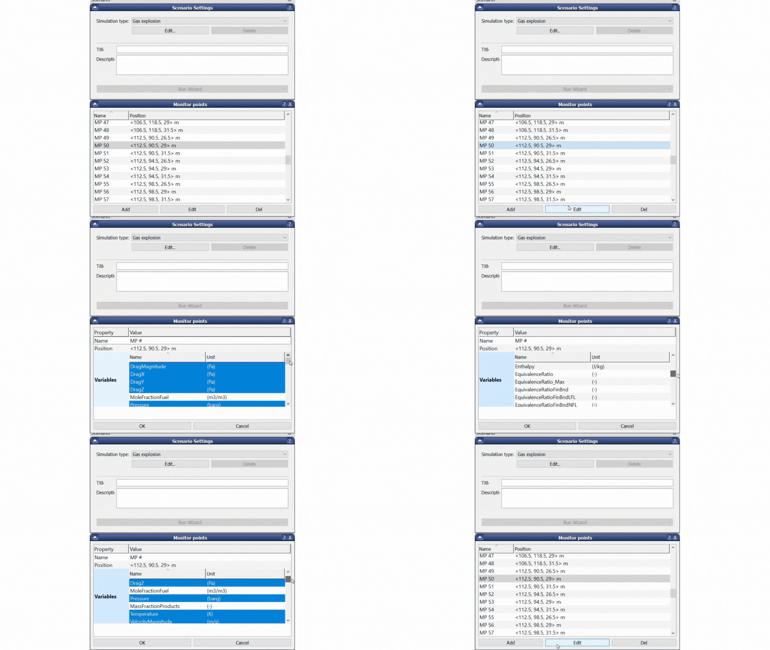
Monitor points are user-defined points where variables are monitored during the simulation. A long list of variables are available with the most commonly used provided at the top of the list.
Monitor points are added by expanding the Monitor points tab in the scenario window and clicking add. In addition to the edit button, the name, position and variables to be output can be edited by double-clicking on the monitor point. Multiple monitor points can be selected to edit more than one monitor point at a time.
Monitor points can be added quickly by right-clicking within the white space in the Monitor points tab and selecting Arrange in grid. Monitor points can also be grouped by right-clicking. Labels can be assigned to filter monitor points. Multiple labels can be assigned to a monitor point.
For fire simulations, monitor points can be be assigned a direction vector for the incident radiative flux
Monitor points should be placed in the centre of a control volume and should not be placed inside fully blocked control volumes or cells with a porosity of 0.5 or less.

Pressure relief panels
Pressure relief panels can be defined within CASD to model the effect of explosion relief panels and yielding walls. Panels can be active or passive. An active panel modifies the porosity when the pressure difference over the panel exceeds the defined limit. A passive panel is used to monitor pressure across the panel (porosity does not change throughout the simulation).
The following panel types are available:
Inactive: used to monitor the pressure over the panel
Unspecified: linear displacement panel with full parameter set
Popout: popout panel with linear displacement with limited parameter set
Hinged: panel with rotational displacement
Plastic: simulates the presence of plastic sheets (as used in experiments)
Overlay: panel overlaid onto existing geometry, the latter does not yield
Popout rigid: rigid panel with linear displacement
Hinged rigid: rigid panel with a rotational displacement
For pressure relief panels, the following properties can be defined:
Name: identifier for the panel.
Position: coordinates of the corner of the panel (lowest coordinate in each axis). The position and size of the panel should be selected so that the panel edges coincide with grid lines.
Size: the panel is defined as a plane of rectangular shape, one dimension should be zero.
Material (hue): changes the colour of the panel by entering the hue value e.g., “300“
Type: as above
Hinges: hinged axis of the panel (+X, -X, +Y, -Y, +Z, -Z)
Side outflow: none, frontal, lateral or both (combined frontal and lateral) outflow can be considered for hinged rigid panels. By default (none) only the projected panel opening area is considered in the average panel porosity calculations.
Opening pressure differences: in bar, the yield pressure in the negative and positive directions.
Initial and final porosity: initial area porosity prior to yielding and final porosity after yielding ranging from 0 (totally blocked) to 1 (fully open). The time taken for the panel to yield completely depends on the pressure across the panel, panel weight and type.
Weight: mass per unit area of the part of the panel that is moved when the pressure acts on the panel (kg/m2). For uniform steel plates, a value of 10kg/m2 is often considered.
Drag coefficient: dimensionless drag-coefficient required for unspecified type panels only. Defined to model the drag force on the panel. A typical value for the coefficient is 2.
Maximum travel distance: the smallest distance from the initial position to the point where the yielded panel no longer significantly affects the effective area porosity at the initial position during panel yielding. Typically in the order of 1m.
Panel sub-sizes: dimensions required for popout and hinged type panels which are assumed to consist of sub-panels mounted on a frame. A width and height are required to be entered. For hinged panels, the width must be specified first.
Variables: variables which can be monitored across the panels including drag, drag impulse, panel porosity, pressure, pressure impulse and panel travel distance
Single field 3D output
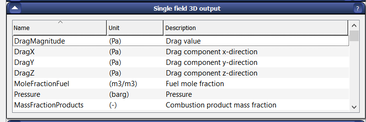
Used to output variables to be used to generate 3D, 2D cut plane and scalar line plots in Flowvis. A wide range of variables can be selected.

For dispersion scenarios the fuel mole fraction, velocity magnitude and velocity vectors are most commonly selected.
For explosion scenarios pressure and flames (massFractionProducts) are commonly selected.
Data output frequency is specified by setting DTPLOT or NPLOT in the Simulation and output control tab. The cc-file can also be used to define outputs at selected timesteps.
Gas monitor regions
The gas monitor region can be used to monitor the amount of fuel within defined volumes. The following variables can be output:
Equivalent cloud volumes
FlamMass
FlamVol
GasMass
To access this functionality the user must right-click in the Scenario pane and select Gas monitor region or Custom gas monitor regions.
To define a gas monitor region a position and dimensions must be provided. The defined position is the lower corner of the volume.
Custom gas monitor regions allows for multiple regions and additional functionality.

